|
Keeps the air gently gliding through your ductwork and past the
Air Probe Sanitizer UV-C lamps. Because the fan never stops (just slows down to very slow), the ultraviolet
lamps are always doing their job zapping slow-moving contaminants.
 Very useful in northern climates in the spring and fall months when
the air conditioner/furnace blower fan does not run. Very useful in northern climates in the spring and fall months when
the air conditioner/furnace blower fan does not run.
When the FanHandler is operating, the average blower speed is much slower. This
allows more time for UV lights to kill germs and mold spores. In many cases, the "kill time" of the
UV rays from the Air Probe Sanitizer probes can be vastly increased. Your filters work about three times
more efficiently. And, a super important point is that during air conditioning, much more moisture is
removed from your home and it is much less likely to be blown off the A/C coil and into the ductwork
where it can provide a great environment for mold.
 Can actually help save energy. The FanHandler, when running
a quality blower motor at half-speed, (which it does most of the time) will use about one eighth the
electricity that it takes to run the same motor at full speed. In other words you can run the FanHandler
controlled motor eight hours for the same amount of money that you can run the same motor for one hour
at full speed. But don't buy one for the energy savings, buy it for healthy indoor environmental quality
(through increased Air Probe Sanitizer and filter efficiency), and comfort. Can actually help save energy. The FanHandler, when running
a quality blower motor at half-speed, (which it does most of the time) will use about one eighth the
electricity that it takes to run the same motor at full speed. In other words you can run the FanHandler
controlled motor eight hours for the same amount of money that you can run the same motor for one hour
at full speed. But don't buy one for the energy savings, buy it for healthy indoor environmental quality
(through increased Air Probe Sanitizer and filter efficiency), and comfort.
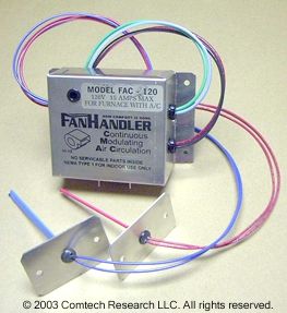
The model FAC-120 (120 volts, 15 amps max.) senses either hot
or cold air in the furnace/AC plenum or duct, and speeds up the fan as required. The fan returns to
minimum speed (user-adjustable) afterwards, as illustrated here. (Use HP-120 or HP-240 for heat pumps).
The FanHandler is very durable and reliable. All FanHandler products are tested
during the manufacturing process at least three times on actual residential-type blowers.
WARRANTY:
FanHandler CONTROLS CARRY A FIVE-YEAR MANUFACTURER'S LIMITED WARRANTY ON PARTS
AND WORKMANSHIP (excludes mishandling, abuse, misapplication, or any costs for removing and replacing
the installed control). Effective 10/1/03
PRICES:
Available from your dealer. The FanHandler is
available at a discount only if purchased with an
Air Probe
Sanitizer. Price breaks are available for case quantities of 12 and 48 units.
Mix or match for quantity FanHandler discounts. Prices do not include
installation or shipping.
 FanHandler specification and information documents in PDF format: FanHandler specification and information documents in PDF format: |
 Info sheet #1*. (The schematic there shows it wired into the existing fan relay, but that is not
necessary (or possible) on some systems). Info sheet #1*. (The schematic there shows it wired into the existing fan relay, but that is not
necessary (or possible) on some systems).
|
Info sheet #2
|
*The schematic diagram in info sheet #1 has been a little confusing
to some people. Here are some clarifications.
The FanHandler is usually installed simply as follows:
(model FAC-120)
- Cut the white fan motor common wire (neutral). Connect the two resulting wire ends as follows:
- Connect the FanHandler's red wire to the white wire coming from the motor (motor common).
- Connect the FanHandler's black wire to the remaining white wire (neutral).
- Connect the FanHandler's green wire to ground.
- Connect the FanHandler's blue wire to the hot wire (L1, usually black).
Turn the FAN switch on the wall thermostat from the AUTO to
the ON position. The schematic indicates a normally-closed motor
relay on the system's fan controller board. When the system is not calling for
heat/cool, then it is ONLY closed when the FAN switch is ON (on many systems).
LEAVE THE FAN SWITCH IN THE ON POSITION.
Replace the phrase "motor common" or "fan motor common" at the bottom of the schematic with the phrase
"neutral (former fan motor common), white".
Connect the temperature sensors in the directions furnished with each FanHandler (below) for
adjusting the blower speed, etc.
|
The FanHandler, like the Air Probe Sanitizer, is to be installed only
by a qualified person, such as your local licensed HVAC (Heating, Ventilating, and Air Conditioning)
professional, IAQ (Indoor Air Quality) professional, or licensed electrician.
INSTALLATION & OPERATION OF
FanHandler controls
For use on P.S.C. or shaded pole motors used to drive direct-drive
fans and blowers. SENSORS FOR FAC-120 AND FAC-240 SERIES FanHandler CONTROLS
- AC/Furnace: FAC-120
& FAC-240 SUPPLIED WITH 1-RED & 1 BLUE SENSOR
- Heat pump: HP-120 & HP-240 SUPPLIED WITH 1-YELLOW & 1 BLUE SENSOR
- LA-120 & LA-240 SUPPLIED WITH 1-YELLOW SENSOR.
- 120-15 & 240-8 SUPPLIED WITH 1-RED SENSOR (heating only) OR 1 BLUE
SENSOR (cooling only) NOT STOCKED. WE SUGGEST USING THE FAC-120 AS BELOW.
- O-1Ovdc-120 & O-1Ovdc-240 NO SENSORS
FanHandler controls are ETL listed for field or factory installation under
file #114704-322 as conforming to ANSI/UL-508 and CAN/CSA C22.2 NO. 14. Installation and wiring
must comply with all local and national electrical codes.
Only qualified HVAC technicians and service mechanics may install or adjust the FanHandler motor speed
control.
|
TO OPERATE THE FAC-120 ON EITHER HEAT ONLY
OR COOL ONLY SYSTEMS
|
| For air handlers with air conditioning only, and no heat: Leave
the two red sensor wires disconnected, and do not use the red (heat) sensor supplied.
For air handlers with heat only (furnaces with no air conditioning): Connect
the two blue sensor wires together, and do not use the blue (cooling) sensor supplied.
|
INSTALLATION
1. DISCONNECT POWER TO THE EQUIPMENT
2. Check operating voltage of fan, and make certain that the control
is of the proper voltage and type.
3. Mount the FanHandler in a location safe from weather, moisture
or excessive heat. Normally this is inside the fan compartment, mounted on or near the blower.
4. Locate sensors
in the supply duct
were they will sense a representative sample of the air temperature being delivered to the conditioned
space. This is done by drilling a 1/2" holes in the proper locations and fastening sensors to duct with
two sheet metal screws each. Do not locate sensors a long distance down the duct from the heating and
cooling source. This may result in the fan speed lagging the actual output. Route low voltage sensor
wires away from high voltage wiring. Wire sensors to corresponding colored sensor wires (blue sensor
to blue wires, red sensor to red wires and yellow sensor to yellow wires).
5. Wire the FanHandler in series with the fan motor. Several wiring
diagrams are included as examples.
6. Double check wiring, then reapply power to the system.
Turn the Fan AUTO/ON switch on the wall thermostat to ON and leave it
there.
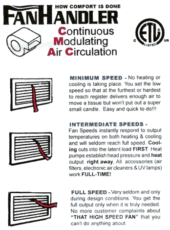
7. Set minimum speed.
Minimum speed
is adjusted by turning the potentiometer located behind the small hole in the upper left hand corner
of the front of the box with a small screwdriver. Turning the pot clockwise increases the minimum speed,
and turning the pot counter clockwise lowers the minimum speed. Set the minimum speed as high as possible,
without causing uncomfortable drafts. Setting the minimum speed too low (although impressive) does not
properly mix the air in the home and will produce unwanted results. A rule of thumb: set minimum speed
so that the furthest run will move a tissue but not cause a draft a foot from the register. The minimum
speed adjustment is for setup and fine-tuning only, it should be set and left alone. If the owner wants
to temporarily override or change the speed of the fan after installation, then a remote speed selector
should be installed (see later in the instructions). That way your original setting is maintained while
allowing the customer to override the speed as desired.
8. Verify operation.
Allow the system
to balance out so it is delivering about 72 degrees and is neither calling for heating nor cooling. Then set
the thermostat to call for heat, as the temperature rises in the duct, the fan speed should increase.
Set the thermostat to shut the heat off and observe that as the delivered air temperature drops, the
fan speed will decrease to your PRE-SET minimum speed. Then set the thermostat to call for cooling,
as the temperature in the duct drops the fan speed will increase and hit top speed at about 50
degrees delivered
temperature. Turn thermostat up turning off the air conditioner. Observe that while the temperature
in the duct approaches room temperature, the FanHandler control will smoothly decrease the fan speed
back to your minimum speed setting.
IMPORTANT -- MOTOR SELECTION
If you or your customer is unwilling to replace an incompatible motor, we recommend
that you not purchase or install FanHandler controls.
You will
occasionally encounter direct drive fan motors built to meet a price rather than a quality criteria.
These motors do not contain adequate copper windings or iron laminates to allow the motor to follow
the fan laws when reducing speed. These motors are usually constructed to loose stator to rotor spacing
tolerances. Or a motor on the job might have been banging on and off for years and not oiled so the
bearings are worn. If a motor heats-up and/or growls at low speed, or if the current increases
as the speed is adjusted from maximum to a lower speed, then it should be replaced with a high
quality motor designed for general use. Quality is the only factor in determining a motor's fitness
for speed regulation. Determine motor fitness on a case by case basis. It is impractical for us to keep
up with changes that equipment manufacturers make in the motors that they install. Baldor is building
a high quality, commercial/industrial quality, motor to our specifications. We offer these direct-drive
motors to FanHandler contractors.
In our experience, the motor does not usually have to be replaced
in most installations. But if it does, we offer the motors at just above our wholesale cost to our
FanHandler customers. Please note that these motors are special order, since we get very few
orders for them.
Motor Power Requirements & Operation Cost Formulas
DEFINITIONS:
S = Speed = RPM = Revolutions Per Minute.
CFM = Cubic Feet Per Minute.
W = Watts = Electrical unit of power.
HP = Horsepower = Mechanical unit of power.
1 HP = 745 Watts = Conversion of electrical power to mechanical power.
Fan Laws:
CFM2 = CFM1 x RPM2/ RPM1 or CFM is directly pegged to rpm.
If RPM is cut in half then CFM is also cut in half. If 1,040 RPM produces 1,200 CFM
then 520 RPM will produce 600
CFM.
HP @ S2 = HP @ S1 x (RPM2 / RPM1)2 This demonstrates that
the horsepower required to turn the fan is related to the square root of the speed change. Or if the
fan's speed is cut in half, then the amount of air delivered is also cut in half but the Horsepower
required is only 1/4 of the original Horsepower required. OR, a fully loaded 1/2 HP fan
motor running at 1,040 RPM and producing 1,200 CFM will only require 1/8 HP to deliver 600 CFM at 1/2
speed of 520 RPM. This demonstrates that the power required to turn the fan reduces a lot faster than
the reduction in CFM being delivered.
WATTS2 = WATTS1 x (RPM2/RPM1)3 or WATTS2 = WATTS1 (CFM2/CFM1)3
This demonstrates that the electrical power required to turn the fan drops by the cube of the speed
change. Or drop the speed (RPM) in half and the Power (Watts) required is 1/8 the original power required.
Our example:1/2 HP fully loaded fan motor running at 1,040 RPM and delivering 1,200 CFM requires 745
watts/2 or 372.5 Watts. Cut this motor's speed in half and you cut the air delivery in half, but the
Wattage required is 372.5/8 = 46.6 Watts.
Therefore, a fan motor must run 8 hours at half speed to use the same amount of
electricity as it would running at full speed for 1 hour.
Now lets bump this up against reality. Lets assume that our example fan
is in an average furnace. On an average winter day it runs about 1/2 of the time. It therefore uses
372.5 watts / 2 = 186 watt-hours of electricity. Now we install a FanHandler that runs the fan full
time. Now lets say there is a call for heat 3 times during that hour and the fan reaches top speed three
times for 3 & 1/3 minutes each time (which it probably won't) 10 minutes per hour = 1/6 hour x 372.5
watts = 62 watts and the other 50 minutes it uses 5/6 of 46.6 watts = 38.83 watts for a total of 38.8
+ 46.6 =100 watts per hour. For a savings of 86 watt-hours. And the home is comfortable, the air cleaner
or filters are working full-time at much higher efficiency.
Monthly cost for the FanHandler equipped fan at $0.10 per KWH = 86 watt
hours x 24 hours x 30 days per month = 61,920 watt-hours or 61.9 KWH x $0.10 = $6.19 per month. If you
ran the full-speed fan round the clock, it would cost 372.5 watts X 24 hours = 8.9 KW = $0.89 per day
X 30 days per month = $26.00 per month. If you ran the full-speed fan 1/2 the time it would cost $13.00
per month. You can use your electricity costs and horsepowers etc. to do the comparisons. It will prove that the FanHandler saves energy!!
Simply put, you can run the fan eight hours at half speed for
the same cost as running it one hour at full speed.
THE IN-DUCT TEMPERATURE SENSORS (2)
The sensors are actually thermistors (resistors that change value as the
temperature changes). They are the small shiny black beads at the tip.*
Like the FanHandler, they are very reliable. If you should ever want to test
them, here are the approximate resistance readings at 62 degrees F. (a
typical value with the air conditioner running):
Blue probe: 7K Ω (cold air
sensor)
Red probe: 45K Ω
(hot air sensor)
At temperatures other than 62 degrees, these readings will be different.
These are values of
sensors supplied with the FAC-xxx models, for reference.
* DO NOT bend or pick at the tiny
black shiny bead at the tip of the sensor probe. You can break the tiny
wires, rendering the probe useless. A nominal charge will be made for a
replacement probe damaged in this way.
FOR PROFESSIONAL INSTALLATION BY QUALIFIED PERSONS
ONLY.
For good reasons, we do NOT sell the FanHandler
directly to the consumer, and so the price is not advertised here. HVAC and IAQ professionals, please call us for pricing
and ordering information. We're
sorry for any inconvenience this may cause.
FanHandler™
Continuously Modulating Air Circulation
How Comfort Is Done
Back to Air Probe Sanitizer main page
|